SF32LB58-DevKit-LCD
Overview
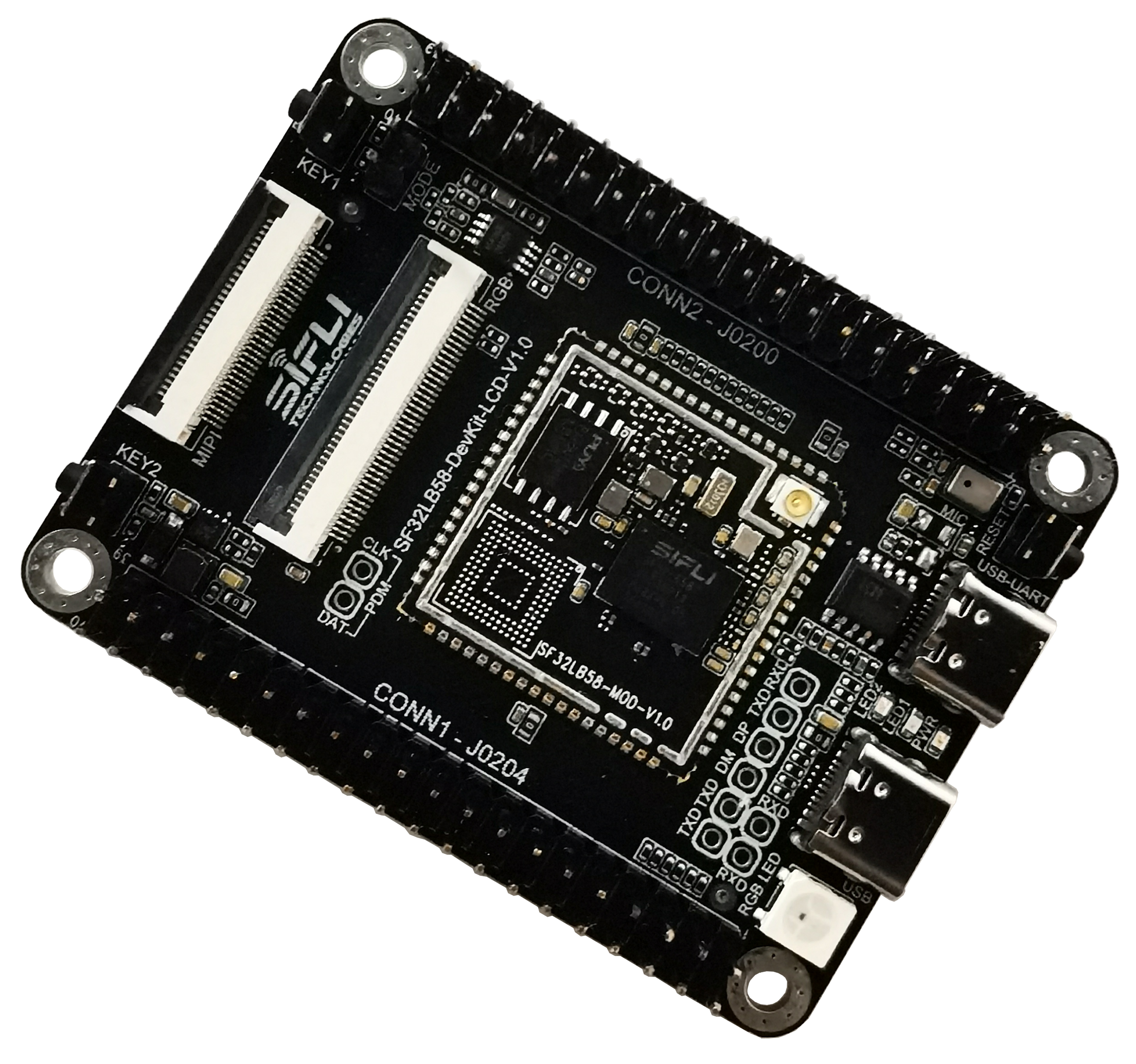
The SF32LB58-DevKit-LCD is a flagship development board built around the SF32LB58-MOD module family. It is intended for products that use DSI, DPI/RGB, or QSPI displays and need a practical bring-up platform for high-resolution UI, audio, storage, USB, and peripheral integration.
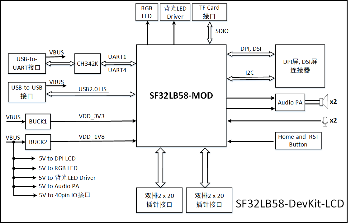
The board brings together the SF32LB58x module, multiple display connectors, analog microphone input, stereo speaker output, MicroSD, dual USB Type-C ports, large-core and low-power-core expansion headers, and accessory interfaces such as CAN and SDIO Wi-Fi expansion.
This makes it a strong fit for high-end wearable HMIs, rich dashboards, connected control panels, and other products that need to validate display, storage, audio, and external-peripheral behavior before committing to a custom flagship board.
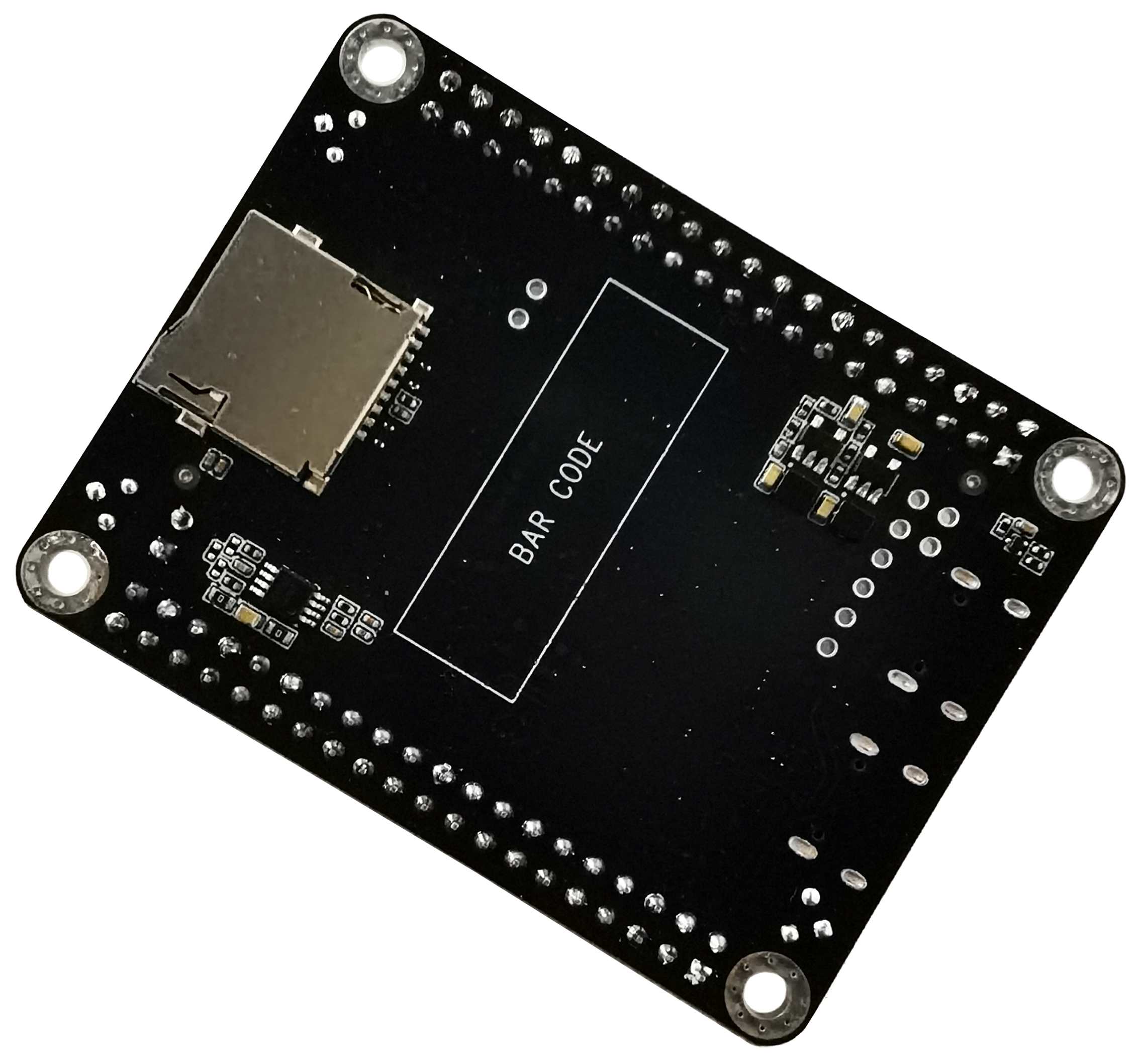
Board and Module Version Notes
| Module Version | Basis | Notes |
|---|---|---|
| V1.0.1 | SF32LB58-MOD-N16R32N1 and SF32LB58-MOD-A128R32N1 using SF32LB586VDD36 | Current version; updated eMMC power-control IO split between PA74 and PA80 |
| V1.0.0 | SF32LB58-MOD-N16R32N1 using SF32LB586VDD36 | Initial module version |
| Board Version | Basis | Notes |
|---|---|---|
| V1.0.1 | SF32LB58-MOD-N16R32N1-V1.0.1 and SF32LB58-MOD-A128R32N1-V1.0.1 | Current version; adds USB plug-detect on PB24, strengthens power delivery for dual-audio output, removes RGB LED level-shift stage, updates DCDC device, and fixes USB slave interrupt behavior |
| V1.0.0 | SF32LB58-MOD-N16R32N1-V1.0.0 with SF32LB587VEE56 | Initial public board version |
Confirm the exact module and board silkscreen revision before choosing a firmware target, storage assumption, or debug wiring plan.
Board Highlights
- SF32LB58-MOD-N16R32N1 or SF32LB58-MOD-A128R32N1 module, depending on board version
- Standard SF32LB586VDD36 platform with dual 16MB HPI-PSRAM and 1MB in-package QSPI-NOR
- Additional 16MB QSPI-NOR or 128MB QSPI-NAND, depending on module variant
- 48MHz main crystal and 32.768kHz RTC crystal
- IPEX antenna connector and module RF matching network
- MIPI DSI / RGB888 display support through dedicated FPC connectors
- Dual QSPI / DSPI / SPI display paths exposed through 40-pin headers
- I2C touch-panel support
- On-board analog microphone input and stereo Class-D audio output
- Two USB Type-C ports: one for USB-to-UART download/debug, one for USB2.0 HS
- MicroSD card slot over SDIO
- Large-core and low-power-core GPIO expansion through two 40-pin headers
- CAN and SDIO Wi-Fi expansion capability
When to Use This Board
Choose SF32LB58-DevKit-LCD when the project needs a realistic high-end display and peripheral validation platform rather than a minimal breakout board.
- Bring up MIPI DSI, RGB888, or QSPI display panels
- Validate touch, audio, storage, and USB together
- Test high-resolution UI behavior on the SF32LB58x platform
- Evaluate CAN or SDIO Wi-Fi expansion
- Compare NOR and NAND-backed module configurations
- Validate firmware on a flagship-class board before custom PCB work
For module-level integration planning, also review SF32LB58-MOD. For chip-family architecture and display/memory capability, see SF32LB58x.
Hardware Configuration
| Area | Configuration |
|---|---|
| Core module | SF32LB58-MOD-N16R32N1 or SF32LB58-MOD-A128R32N1 |
| Standard MCU | SF32LB586VDD36 |
| In-package memory | 16MB + 16MB HPI-PSRAM, plus 1MB QSPI-NOR |
| Additional storage | 16MB QSPI-NOR or 128MB QSPI-NAND, depending on module variant |
| Display | MIPI DSI, DPI/RGB888, and QSPI panel support |
| Audio | On-board analog microphone path plus stereo speaker output |
| USB | USB-to-UART Type-C and USB2.0 HS Type-C |
| Storage | MicroSD card slot over SDIO |
| Antenna | Module RF path with IPEX connector |
| Expansion | Two 40-pin headers for large-core and low-power-core expansion |
Getting Started
Required Hardware
- SF32LB58-DevKit-LCD board
- LCD module using MIPI DSI, RGB888, or QSPI, as appropriate
- USB 2.0 data cable, Type-A to Type-C or equivalent
- Host computer running Windows, Linux, or macOS
Optional Hardware
- Two speakers
- TF / MicroSD card
- J-Link or compatible SWD debugger
- CAN transceiver board
- SDIO Wi-Fi module
Basic Setup
- Connect the target display panel to the correct LCD connector.
- Connect the USB-to-UART Type-C port to the host computer.
- Open SiFli's download tool and select the correct COM port.
- Install or remove the Mode jumper depending on whether you want download mode or normal run mode.
- Power the board and download or run the target firmware.
- After display bring-up, validate touch, audio, storage, and any expansion peripherals required by the product.
Use a real data-capable USB cable. Some Type-C cables provide power only and will not expose the UART or USB data path.
Power
SF32LB58-DevKit-LCD is powered from USB Type-C.
- Both on-board USB Type-C connectors can supply power to the board
- For firmware download and UART logging, use the USB-to-UART Type-C port
- Plan the USB2.0 HS Type-C port separately when validating native USB functions
Download and Debug
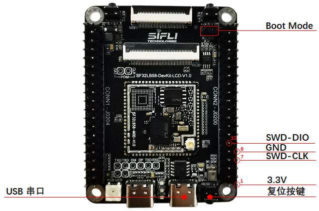
The primary firmware download and serial-log interface is the USB-to-UART Type-C port.
- Download mode: install the Mode jumper, then power or reset the board
- Software debug/log mode: remove the Mode jumper, then power or reset the board
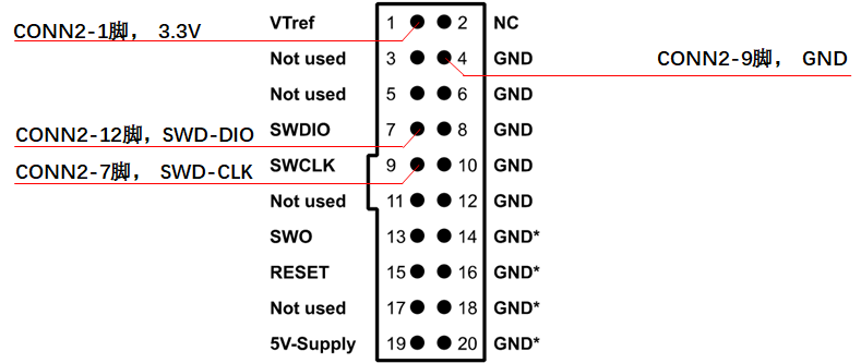
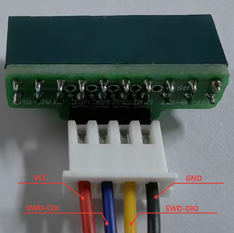
The board also supports J-Link / SWD debug.
Key Module and Expansion Signals
The board exposes both module-level signals and two 40-pin expansion headers. Use the module datasheet and schematic package for the exhaustive pin map; the summary below covers the most design-relevant groups.
| Signal Group | Typical Pins / Signals | Main Use |
|---|---|---|
| Download and debug | PB36, PB37, SWDIO, SWCLK, Boot_Mode, RSTN | UART download, software debug, SWD bring-up |
| MicroSD | PA75, PA76, PA77, PA70, PA81, PA79, PB58 | SDIO card interface and card detect |
| RGB LCDC1 | PA12–PA15, PA22–PA67 | RGB888 display path |
| MIPI DSI LCDC1 | DSI_D0, DSI_D1, DSI_CLK lanes | MIPI DSI display path |
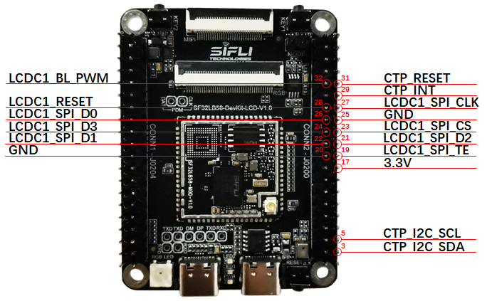
| QSPI LCDC1 | PA82, PA84, PA86, PA88, PA90, PA91, PA51, PA52 | QSPI display path on the large-core side |
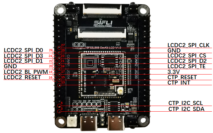
| QSPI LCDC2 | PB02–PB10, PB23, PB27, PB30, PB31, PB34 | QSPI display path on the low-power-core side |
| Touch | PA16, PA17, PA59, PA60, PA92, PA93 | Reset, interrupt, and I2C touch-panel signals |
| Audio | AU_DAC1/2, AU_ADC1/2, MIC_BIAS, PB23 | Analog audio input/output and PA enable |
| CAN / general expansion | PA02, PA11 and header GPIO groups | CAN and peripheral expansion |
Display Interfaces
The board supports three main display paths:
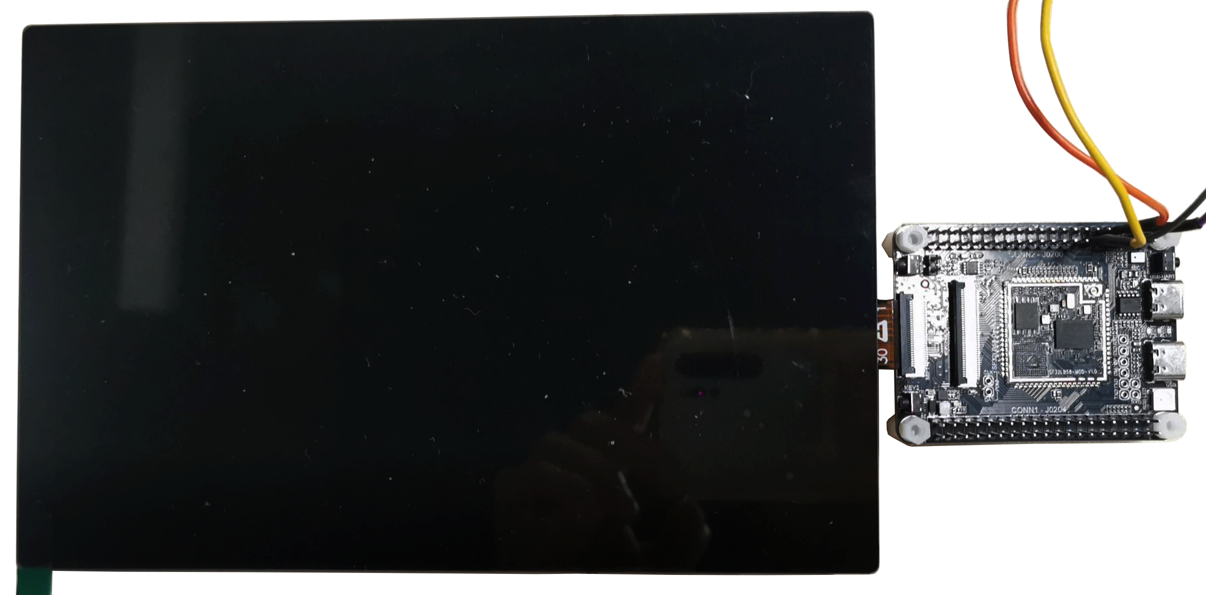
- MIPI DSI through a 30-pin, 0.5mm-pitch FPC connector
- RGB888 through a 40-pin, 0.5mm-pitch FPC connector compatible with a common 正点原子-style pin order
- QSPI / DSPI / SPI through the two 40-pin expansion headers
Supported display guidance from the SiFli source includes:
- MIPI DSI panels up to 2-lane transfer and up to 1280 × 800 resolution
- RGB888 panels up to 1280 × 800 resolution
- QSPI panels up to 512 × 512 resolution
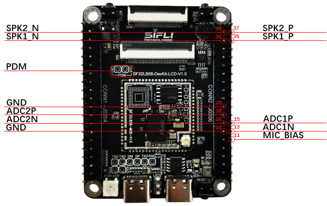
Audio
The board supports:
- One on-board microphone input path
- Two audio ADC input paths, with one multiplexed against the on-board microphone path
- Two speaker outputs
- One PDM signal path that is multiplexed with RGB signals and therefore unavailable while the RGB display path is active
CAN and SDIO Wi-Fi Expansion
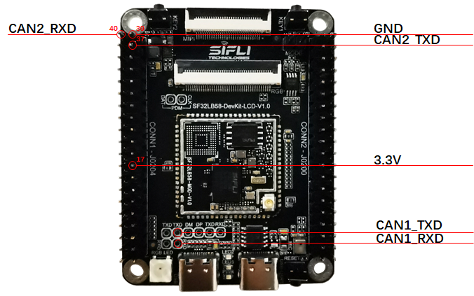
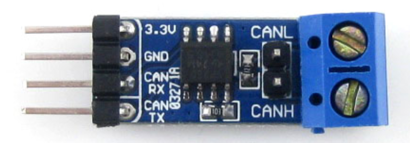
The underlying SF32LB58 module includes a CAN controller, and the board exposes the interface for use with an external transceiver.
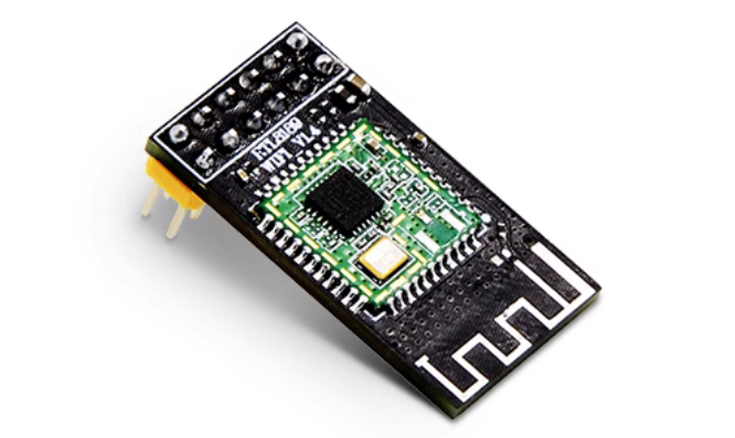
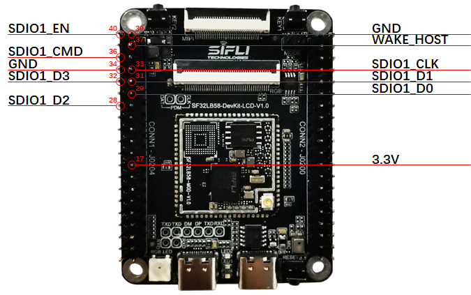
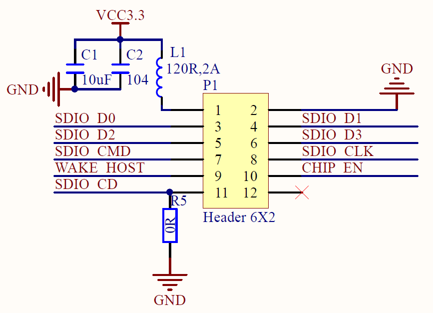
The board also supports SDIO Wi-Fi expansion through the header interface.