Run Bluetooth Signaling Tests
Signaling mode creates a real Bluetooth link between the DUT and a communications tester. It is the SDK route for protocol-conformant TX/RX validation and BQB/QDID work; it is different from vendor non-signaling or single-item RF tests.
Test setup
Prepare the DUT, a Bluetooth communications tester (the source guide uses CMW500), a Windows PC, USB-to-UART cable, and an RF coax cable. Expose VBAT, GND, and UART1 TX/RX on the DUT. Default UART1 pins vary by package:
| Device/package | UART1 TX | UART1 RX |
|---|---|---|
| SF32LB551 | PA17 | PA18 |
| SF32LB555/557 | PA34 | PA30 |
| SF32LB56xU (QFN) | PA17 | PA18 |
| SF32LB56xV (BGA) | PA34 | PA30 |
| SF32LB58x | PA32 | PA31 |
| SF32LB52x | PA19 | PA18 |
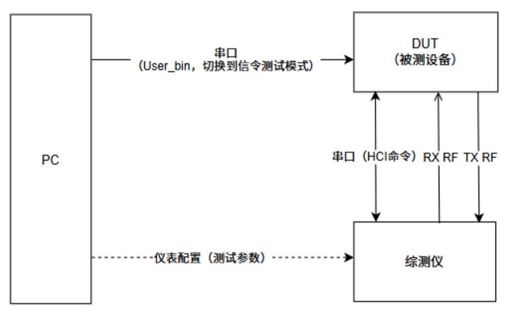
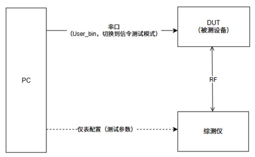
Use the project's actual pin configuration when it differs from this default map. BLE signaling needs a serial EUT-control connection to the tester; Classic BT signaling can control the DUT over the air after it enters test mode.
The key distinction is the control topology: BLE connects the UART/HCI control path to the tester, while Classic BT lets the tester discover and connect to the DUT over the air. The source guide's SF32LB52x diagrams are shown below; use the target project's pin table for other families.
Family scope
The UART pin table is the consolidated family/package comparison. The topology and tester screenshots that follow are SF32LB52x source examples; use them to understand the signal path, not as a package-independent pin or menu reference.
Put the DUT into test mode
BLE
- Boot the DUT and keep DFU/application firmware awake.
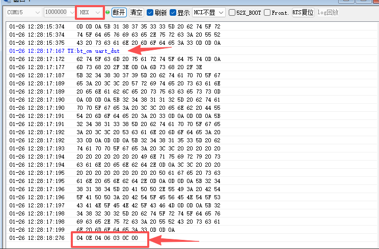
- Connect UART1 to the PC and send the FinSH command
bt_cm uart_dutwith SiFli_Trace or another serial tool. - Switch the terminal to hexadecimal display and verify
04 0E 04 XX 03 0C 00. - Disconnect the PC and connect the same UART1 to the tester's USB-to-RS232 EUT-control port.
Classic Bluetooth
- Boot the DUT and keep the screen/CPU awake.
- Connect UART1 to the PC and send
bt_cm dut. - Verify the
Write scan enable successresponse, then connect the RF coax to the tester. Reboot before entering a different test mode.
Establish the signaling connection
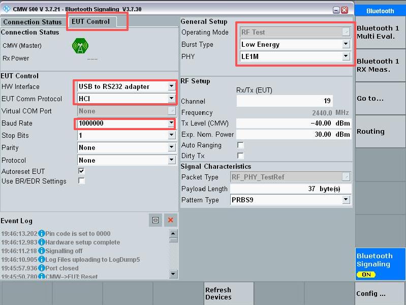
In the tester's Bluetooth Signaling application, turn signaling on. For BLE, select USB-to-RS232 adapter, 1,000,000 baud, and Low Energy burst type under EUT Control. Connect UART1 to the tester, run Connection Check, and wait for LE comm test passed. For Classic BT, set HW Interface to None (EUT Control off), search for the DUT address with Inquire, and select Connect Test Mode.
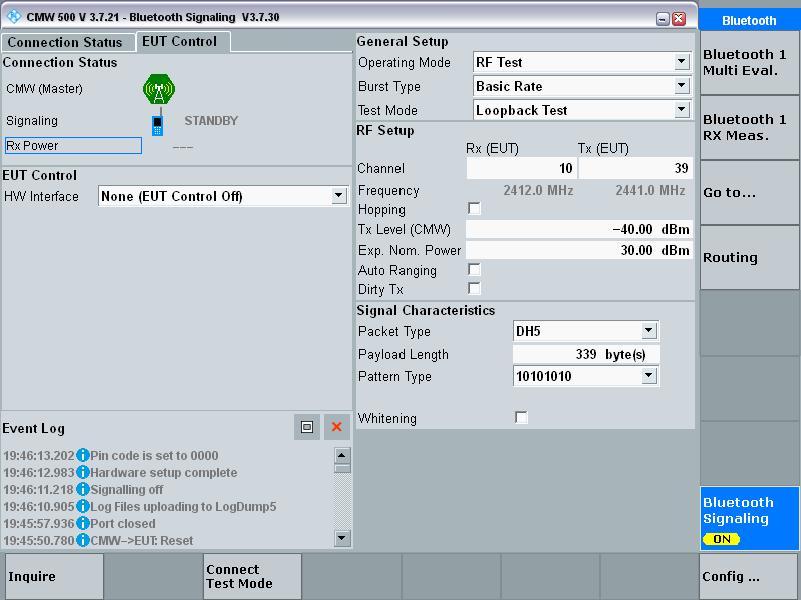
Run TX measurements
Open Bluetooth 1 Multi Eval. and enable the measurement. Select the required BLE 1M/2M or Classic BT BR/EDR burst type, channel, packet type, and payload length. The same tester TX screen is used after either BLE or BT signaling connection.
Run RX sensitivity measurements
Disable TX before returning to the signaling screen, then open Bluetooth 1 RX Meas.. Select BER for Classic BT or PER for BLE, configure the channel and packet type, and enable Rx Quality. Reduce the tester's Tx Level (CMW) in small steps; the last value before the BER/PER indicator becomes invalid is the measured sensitivity. Record whether the result is conducted or radiated and include cable loss.
Record and reproduce
Keep the chip/package, UART pin map, SDK revision, firmware identity, tester model and configuration, RF connection, channel, PHY, packet settings, TX level, BER/PER, and board revision with the result. The official family pages are SF32LB52x, SF32LB55x, SF32LB56x, and SF32LB58x.